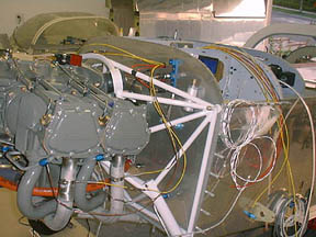
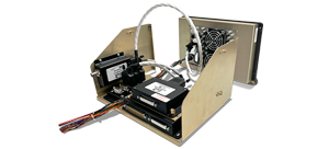
Engine Probes & Packages
Dynon offers a variety of engine probes. These can be purchased individually, but are usually bundled in complete engine packages. Engine probe packages include the wiring harnesses and all probes required. The purchase of an engine package saves approximately 10% over buying its contents separately.
At present, Dynon offers engine probe packages for the following engines:
- EMSKIT-L4C, Lycoming/Continental, 4 Cylinder, Carbureted
- EMSKIT-L4F, Lycoming/Continental, ULPower, 4 Cylinder, Fuel Injected
- EMSKIT-L6C, Lycoming/Continental, 6 Cylinder, Carbureted
- EMSKIT-L6F, Lycoming/Continental, 6 Cylinder, Fuel Injected
- EMSKIT-RTX, Rotax 912, Carbureted
- EMSKIT-RTXis, Rotax 912 iS, Fuel Injected
- EMSKIT-J22, Jabiru 2200
- EMSKIT-J33, Jabiru 3300
The probes, harnesses, and sensors included in each of these kits are detailed in our price list and
order form. Additionally, individual sensors and harnesses are available for purchase to accomodate customers that do not have one of the above engines.
Programmable Alarms
A significant advantage of these systems over the standard analog gauges is its ability to continuously monitor each parameter for the pilot and post an alarm anytime an abnormality arises.
To facilitate a wide variety of engines and pilot preferences, each engine measurement is individually setup during the installation process. Pilots can define the color coded operating ranges, whether or not an alarm is generated, and how the alarm behaves once active. Alarm behavior can be set to either be latching, which requires operator acknowledgement, or self-clearing, which lets the alarm remove itself once the offending parameter returns to its normal operating range.
Whenever an alarm condition occurs it is annunciated in a variety of ways:
- A red bar is posted across the bottom of the screen
- The alarm menu is posted across the bottom of the screen
- The measurement value(s) in the alarm state blinks red
- An alarm contact output is closed, which turns on a user-supplied alarm light
- An audible tone is annunciated through the audio panel or intercom when connected
Pilots can deal with alarms in multiple ways. Pressing silence allows all visual annunciations to remain, but the audio tone is muted. Alternatively, the alarm can be fully acknowledged, in which case the audible signal, red alarm bar and external alarm light are all dismissed. Regardless of any action, the alarming measurement value will remain in the blinking red alarm state until the alarm condition is no longer present.
New Programmable Alarms - CHT Shock Cooling & Span Alarms
Current EMS models are now equipped with CHT shock-cooling alarm capability to alert pilots whenever cylinders drop their temperature too suddenly. Separate temperature span alarms are also included that actively monitor across all EGTs & CHTs. Unique temperature span set points can be programmed for lean and normal operating modes.
Easy Setup
With 27 different inputs and 3 outputs possible, builders will quickly come to the realization that there is a fair amount of setup involved. To make this process as straight forward and easy as possible, Dynon has implemented a number of features to simplify this to the extent possible.
They include:
- Dedicated Input/Output Connections - All but 3 of the wiring inputs into the back of the instrument are dedicated to a particular measurement thereby simplifying the otherwise complicated task of wiring. Only three connection pins are general purpose in nature and require additional attention by installers during setup.
- Wiring Harnesses - Dynon offers pre-wired harnesses with the full complement of wires possible. Two harnesses are offered; one 25 pin cable for all thermocouple connections (EGT/CHT) and a 37pin cable for all remaining input/output connections. The thermocouple cable's 25 pin connector is directly compatible with GRT's EIS-4000 systems to simplify upgrading to Dynon's graphical system.
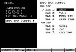
- Easy setup menus - Builders begin by defining high level "Global" parameters like how many cylinders, gas tanks and Info Bars are required. The menu system then automatically configures the detailed setups accordingly to limit redundancy and avoid confusion.
- An Easy to Follow Installation Guide - Is freely available on our web site and continuously kept updated to assist builders every step of the way.
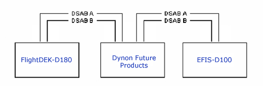
DSAB Connectivity
Dynon Avionics products are equipped with the Dynon Smart Avionics Bus (DSAB). DSAB allows Dynon products to be connected to each other. When connected, DSAB allows all display elements and features from any connected products to be utilized across all screens in the system.
Dynon instruments connected with DSAB are effectively be transformed from single instruments into multi-function units capable of displaying information from any connected unit. This capability is included with every Dynon Avionics product at no additional cost.
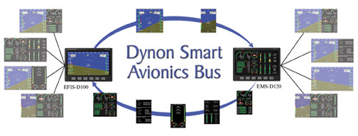
Page Sharing
DSAB effectively allows display pages from one Dynon instrument to be shared and viewed on another Dynon instrument. A terrific example where this works really well is for those cockpits equipped with an EFIS positioned on the pilot's side of the panel and an EMS located directly in front of the copilot. Both pilots have full access to the identical set of EFIS and EMS display pages immediately available in front of them. This will be appreciated by all those who have flown from the copilot's position while straining their necks to read the instruments on the far left side of the panel. The pilot will benefit too, as all engine information can be presented on the EFIS in either full screen or split screen format.

Hotkeys
Dynon provides a Hotkey function for those pilots who wish to more rapidly and conveniently switch between key monitoring pages and or other instrument functions. Hotkeys provide a secondary method in addition to the softkey menus to facilitate more immediate access to the desired page or function. The Hotkey capability is initially activated in the setup process as a higher level function should the pilot so desire.
Two dedicated Hotkeys are available for:
Rapid Page Switching
Pressing the furthest left key sequentially switches between the System Overview Page, Auxiliary Monitor and Fuel Computer Pages. These three pages are considered those most frequently visited in flight.
Instrument Function Switching
Pressing the furthest right button automatically switches the display to other Dynon instruments like the EFIS series if connected. This is initially limited to a single EFIS instrument but will expand in the future to all Dynon instruments with the Dynon Smart Avionics Bus (DSAB).
Note: Switching the EMS-D10 over to display the Dynon EFIS provides a very affordable and convenient way in which to supply the copilot with a flight instrument. It does not provide a completely redundant EFIS instrument as it fully depends upon the EFIS instrument/electronics to be operational and continue outputting data which the EMS-D10 can read and display.
While the EMS-D10 may display the EFIS screen it does not forward control and editing functionality which all remain within the actual EFIS instrument.
Info Bars
Info Items are available as either text, analog vertical bars, or on/off contacts indicators. During setup, Info Items may be configured to display any of the following measurements:
- Volts
- Amps
- Coolant Temperature
- Coolant Pressure
- Fuel Pressure
- Carburetor Temperature
- Outside Air Temperature
- Turbine Inlet Temperature
- Fuel Tank 3
- Fuel Tank 4
- Timers
- Fuel Computer
- Contacts
- Flaps Indicator
- Trim Indicator
Multiple Page Presentation
Introduction
Dynon has adopted a multi-page approach to extend the power and usefulness of the instrument. Given the compact size, the multi-page approach works exceptionally well in balancing oversight of key parameters without compromising access to detail.
The multi-page concept also permits pilots to focus on a particular function or set of related parameters. A good example is the Fuel Computer page wherein the pilot can see fuel tank levels for up to 4 tanks, fuel pressure, fuel flow, fuel used, fuel remaining, time remaining and fuel required to destination all on one optimized display.
Particular attention has been applied to the design of each display page by arranging elements in an ergonomic manner to optimize pilot scanning. Criteria used to accomplish this were:
- Distinctive shapes to quickly differentiate measurements
- Functional grouping of related items
- Descriptive labeling
- Use of English & Metric units
- A degree of builder/pilot screen customization
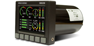
Unlike some other systems that either go overboard with all identical indicators or present the information in a non-logical format, Dynon's EMS-D10 is designed to preserve many of the traditional conventions while taking advantage of the newer graphical display technology. This techno-traditional blend combined with the instrument's continuous internal scan of all parameters provides an excellent value in a small sized package capable of sliding into a standard 3-1/8" panel hole.

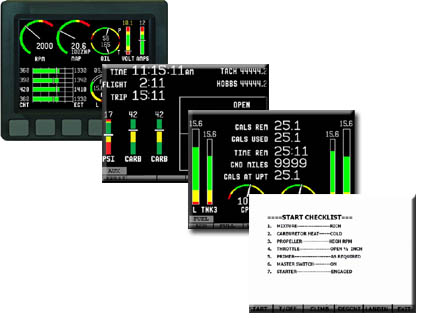
System Overview Page
As the name implies, this is the System Overview or the primary page that pilots are likely to pay the most attention to during flight. This screen is always presented upon startup of the instrument. Pilots may switch to other monitoring pages using either the softkey menu system or a dedicated hotkey for additional detail.
The color ranges and alarms are pre-selected during setup to match your specific engine criteria. The EGT and CHT each facilitate up to 6 channels. Each measurement may be individually deactivated in the setup menu if not desired or if the sensor is out of service.
One of the unique features of the EMS-D10 is the "Info Bars" which are designed to afford greater flexibility in accommodating a wide variety of engine types and pilot preferences. Info Bars are represented by colored vertical bars each with an identifying label, sliding bar and digital value.

Auxiliary Page
The Auxiliary Page presents additional information of interest to the pilot as an extension to that provided on the System Overview Page. This page presents three key groups of data which include:
- Timers
- Info Bars (up to three if desired)
- Contact Sensor Status
Timers
The System Clock presents a real time clock which may be set for local or zulu time and be in either a standard or military format. The Flight Time keeps time of your current flight since the engine was turned on. The Trip Timer maintains an ongoing timer of successive Flights since it was last manually reset via the softkey function (TRPST). This is ideal for tracking cross country trips with multiple flights (legs).
The Tach Time tracks RPM related time while the Hobbs Timer tracks total engine time and is activated by oil pressure.
Info Bars
During setup the builder may select up to three "Info Bars" to be presented in addition to the 4 possible info bars of the System Overview Page. See Info Bars for more detail.
Contact Inputs
The EMS-D10 accepts two inputs from builder supplied contacts to provide status information. These can be utilized to represent aircraft functions like canopy closure, gear down, fuel pump etc. User-defined labels and colors allow these to be operated in the desired manner.

Fuel Computer Page
The Fuel Computer Page presents a comprehensive view of all fuel related parameters in one place. Pilots can quickly assess fuel level, fuel flow and fuel time remaining in one convenient view.
All textual data in the center of the page represent the computed data (requires optional fuel flow sensor) whereas the analog gauges all depict sensor fed data. Both Metric and English units are supported and are selected during installation as a global parameter.
Pilots can update the fuel computer via the softkey menu anytime fuel is added or removed from the plane. This is accomplished by selecting either:
ADD - add or subtract fuel from the Fuel Computer total by any value
FULL - reset the Fuel Computer to a predetermined value representing the fully filled condition
PRESET - reset the Fuel Computer to a predetermined value representing a level commonly filled to, i.e. half filled tanks
For the fuel level to work properly, the sensors need a one-time calibration after installation. The CALIB softkey facilitates adding fuel in set increments. The EMS-D10 records each signal value as the tanks are filled.
The GND Miles and Gals at WPT (waypoint) are only available if the EMS-D10 is fed a signal by an owner supplied GPS signal. The software to support this feature is currently available.

Checklist Pages
Users of the EFIS-D10A series will instantly be familiar with the identical checklist capability presented by the EMS-D10. Using Dynon's
free PC-based Product Support Program, users may define up to 25 different checklists and download them to the EMS-D10 via a serial port connection.
These pages permit pilots to produce highly customized lists covering their particular aircraft. While most frequently used for "Checklists", these screens can cover any subject of interest whether it be waypoint info, a list of radio frequencies or other useful reminders.
Setup Pages
FLEXIBILITY WITHOUT COMPLEXITY
Unlike many other systems currently available, Dynon's EMS-D10 does not constrain the builder to a narrowly defined set of criteria where the number of cylinders, units of measurement or other criteria are already predefined or even prescreened on the display. Considerable flexibility is designed in to cover a wide variety of engines and user preferences without adding complexity.
Dynon has strived to make the setup of this instrument as straight forward as possible. This is accomplished by breaking down the setup process into three basic categories covering Global parameters, Sensor parameters and the real time System Clock.
GLOBAL SETUP
The global parameters are selected at the beginning of the setup process and used by the onboard computer to configure the remaining setup menus to reflect the chosen configuration. This single feature simplifies and shortens the process by eliminating unnecessary or redundant steps.
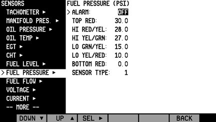
SENSOR SETUP
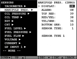
The sensors are each setup separately except for the EGT's and CHT's which are grouped together in their respective groups. From the Sensors Setup Menu, builders are given several choices similar to the Manifold Pressure Sensor Page depicted above.
Typical sensor selection criteria include:
DISPLAY - On/Off allows the builder to activate this function and the pilot to disable it should it become inoperative
ALARM SETPOINT - alarm value to annunciate audible and visual alarms
COLOR RANGES - sets the color range bars on the analog gauges
SENSOR TYPE - presents sensors for which calibration tables exist or known to work with the EMS-D10 instrument


 Proudly built in the U.S.A.