- PRODUCTS
- ❱ SKYVIEW
-
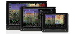
- Featuring HDX - The Premier SkyView Experience
-
- ❱ D30 BACKUP DISPLAY
-

- The D30 can serves as a backup set of flight instruments in SkyView HDX systems.
-
- ❱ ACM JUMPSTART KIT
-
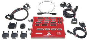
- The proven Advanced Control Module (ACM) is now available to all Dynon Homebuilders
-
- ❱ PORTABLE

- The D3, Dynon’s popular Pocket Panel. Now featuring Synthetic Vision.
- ❱FastTrack INSTALLATION PRODUCTS
-
- Installation aids to significantly reduce install time.
-
- ❱ PROMOTIONS & OFFERS
-

- Trade-up programs available from Legacy Dynon Products.
-
- ❱ SKYVIEW
- NEWS
- LEARN
- BUY
- SUPPORT
- ABOUT
- [ The DYNON Group ]


 Proudly built in the U.S.A.