Designing a SkyView System for your aircraft is not complicated, but there are some details you should know. The following will help guide you in determining what components you need. For actual installation and setup information, we suggest you download the complete SkyView Installation Guide found on our
Common Questions
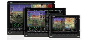
How Many Displays? There are two reasons to have more than one Display: real estate and redundancy. Up to three displays can be networked together. It's true that just one display can show everything, namely the Primary Flight Display (PFD), Moving Map, and Engine Monitoring. However, adding a second display allows both to be dedicated for specific purposes. For example, the left display could show the PFD while the right display shows the Moving Map and Engine Monitor. In the unlikely event of a display failure, the remaining display can still show all data.
Which Transponder? A SkyView Mode-S transponder saves panel space with control and annunciation appearing on the SkyView displays. There are two models: the SV-XPNDR-261 for high performance aircraft, and the SV-XPNDR-262 for aircraft flying less than 15,000' and 175 Knots. The only difference between the two is the output power. Both add TIS traffic information, which graphically shows other aircraft position, altitude and trajectory in standard TCAS 1 format. (Note, TIS traffic is only available in the US in Class B and C airspace with radar coverage. SkyView can also receive traffic information from the Zaon XRX, NavWorx, and GTX 330 products.) Also, both products are certified. Note - full ADS-B Out compliance will require that a TSO-C146A GPS (WAAS) be connected. NOTE ON US COMPLIANCE: Currently the FAA ADS-B requirements specify the higher power Class 1 transponder. For US customers, we recommend only the Class 1 SV-XPNDR-261.
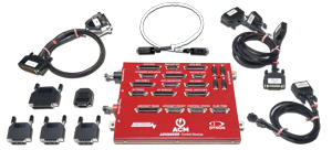
Do I need an ARINC-429 Module? The SV-ARINC-429 makes SkyView compatible with certified GPS receivers, such as the Garmin 430/530. If you have one of these GPS receivers, you should purchase the SV-ARINC-429 Module. It mounts within the avionics bay, and does not use any panel space.
How Are Displays Mounted? The SkyView Displays use a simple but elegant mounting scheme. Simply cut a hole to size for the display, drill holes for the mounting screws, and attach nut plates. No tray is needed. The Displays unscrew from the front to allow easy removal and access to the inside of your instrument panel. You can find hole dimensions for the two screens in the
SkyView Installation Guide.
How Many Network Cables? Each Display has two D9 Network Ports. Each Module has a single D9 Network Port. A cable is typically required between two Displays, between a Display and an ADAHRS Module, and between a Display and an EMS Module. SkyView Network Cables are made of aircraft quality Tefzel wires and come in a variety of lengths:
- SV-NET-6inCC is 6 inches long
- SV-NET-8inCC is 8 inches long
- SV-NET-10inCC is 10 inches long
- SV-NET-1CC is 1 foot long
- SV-NET-2CC is 2 feet long
- SV-NET-3CC is three feet long
- SV-NET-6CC is six feet long
- SV-NET-10CP is ten feet long
- SV-NET-15CP is fifteen feet long
- SV-NET-20CP is twenty feet long
- SV-NET-25CP is twenty-five feet long
- SV-NET-30CP is thirty feet long
The first two have D9 connectors on both ends. The latter five have a D9 connector on one end, and on the other end pins are pre-crimped to the wires. Once the cables are routed through the aircraft, the second D9 connector can be easily affixed to the pins.
We also offer a Network Hub, SV-NET-HUB. This 5-port hub allows a complete system to be easily wired using the cables above. The SkyView Network is a true network, and connections can made at any location. Redundancy is assured through duplicate network and power wires in each 9-wire cable. There are two ports on the back of each Display, that are electrically connected to each other and isolated from the Display electronics itself. So even if a Display were to be turned off for any reason, the two network ports on the back are still communicating with each other.
How Many ADAHRS? One SV-ADAHRS-200 will provide flight data for up to three Displays. However, you can add one or more SV-ADAHRS-201s in order to provide redundancy. When connected by the SkyView Network, the primary ADAHRS will provide flight data to every Display. In the unlikely event of ADAHRS failure, the secondary or tertiary ADAHRS will provide flight data to every display.
Components
System Architecture: The following image shows the components that comprise the SkyView System:
 Wiring Harness:
 Each SkyView Display comes with a Main Wiring Harness. It consists of a D37 connector and a variety of wire leads. One USB Port is included with 3-foot leads. The other leads are used for Primary Power, GPS Serial Input, four General Purpose Serial Inputs, Audio Output, Four Discrete General Purpose Inputs, Panel Dim In/Out, and a Backup Battery Connector. 9-Wire Network Cables are used to connect between Displays and Modules.
Ethernet Connection: SkyView systems with multiple displays should have their Ethernet ports connected together to allow data uploads to be made to only one display and then automatically transferred to the second. The Ethernet connection is in addition to the 9-pin SkyView Network connections which must be made. We offer the SV-ETHERNET-3CC which is an aircraft grade Low Smoke Zero Halogen ethernet connection.
SV-NET-SERVO: This kit helps wire the autopilot servos. It includes 20" of Tefzel wires: two pairs of twisted 22 gauge network wires, one 22 gauge quick disconnect wire, and two 20 gauge wires for power and ground. Also included are three D9 connectors (one male, two females), 18 pins, a pin insertion tool, shrink tubing, and tie wraps. One kit is required for each servo. A crimping tool is required (not sold by Dynon) to attach the pins to the wire.
Test Cable: Each SkyView Display is shipped with a ten foot test cable. This cable is to be used for connecting the Display to the ADAHRS or EMS Modules before installation, to ensure proper functionality. They are NOT made of Tefzel wiring, and so should not be use for actual installation in the aircraft.
Backup Batteries: One SV-BAT-320 Backup Battery can be connected to each Display. A Backup Battery will supply over an hour of electrical power to one Display and the Modules connected into the SkyView Network, including a SV-GPS-250. A Backup Battery will not supply power to another Display in the System, so one SV-BAT-320 should be installed for each Display.
GPS Receiver: A GPS Receiver with a standard NMEA Aviation Output connects to a Serial Input on the SkyView Main Harness. We strongly recommend the SV-GPS-250 SkyView GPS Receiver because its power is provided by the SkyView System, including a Backup Battery in the case of an aircraft electrical system failure. And because it outputs GPS data at 5 times per second, unlike most other GPS receivers (Garmin, etc.) which output data at only 1 time per second. Other GPS receivers can be connected as back-ups via one of the other four serial ports.
OAT Probe: Each SV-ADAHRS-200/201 includes a SV-OAT-340 Outside Temperature Probe, including a 6-foot cable to connect between them.
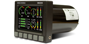
EMS Module Setups : SkyView ships with default Lycoming 4-Cylinder engine sensor settings and screen layout. These are easily customized as desired, and setups for other standard engines can be downloaded from our
Support Forum.
Mechanical Specifications: Links to mechanical drawings for the SkyView Modules can be found on the left of this page. A summary of specifications is also on our
Specifications Page.
Location Requirements - SV-D1000 and SV-D700: Observe the following guidelines when choosing a location for a SkyView display:
- Displays require about 2.4” of free space behind the panel, depending on mounting surface thickness.
- The SkyView Display Harness (SV-HARNESS-D37) extends 3” from the back of the display.
- Leave an inch beyond the physically required volume for the display’s heat sinks and fans to operate.
- Avoid placing the display near heater vents or any source of extremely hot air.
- The display should be easily viewable without any obstructions.
- Displays have no internal sensors and do not need to be mounted in the same orientation as the ADAHRS or other modules.
- Displays only support a landscape viewing orientation; do not mount in portrait orientation.
- SkyView systems support up to three displays.
Typical Configurations: The SkyView Worksheet lists typical configurations and all the components that are required for each configuration. We list everything in the worksheet, so that you can be confident that you know both what you need and how much the entire system will cost.


 Proudly built in the U.S.A.